
")
")

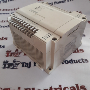
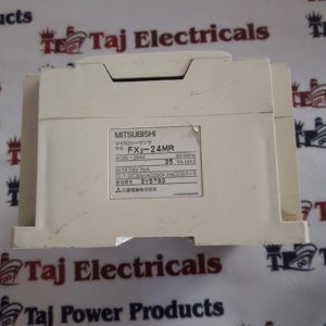
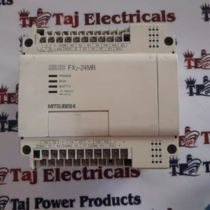
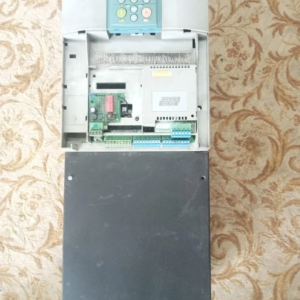
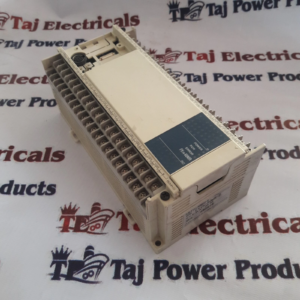
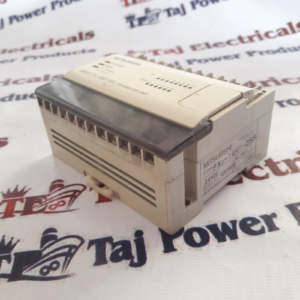
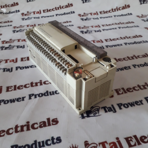
Mitsubishi FX2-24MR PLC SUPERIOR QUALITY PRODUCT SHIPPING WORLDWIDE
Input: 12 digital input S/S
Output:12 Relay Output
Power supply : 85 – 264V AC, 50/60 Hz
FX-24MR-ES/UL Internal relays: 1536 aux relay
Data register: 1000 MW
FX-24MR-ES/UL Timers: 256 timer relay
States: 1000 bit
Counters: 256 standart
FX-24MR-ES/UL High speed counters: Max 6 32 bits up/down counting ,
Max frequency 20 Khz/ 2 khz
Operation processing time: Basic instruction :0,48 microsec.
-Applied instruction:10-100 microsec.
Max. allowable momentary power failure period: Fuse (size) rateing:
(Æ 5 ´ 20 mm (0.2 ´ 0.79 inches))
FX-16M, 24M, 32M/E =3.15A,(type 50CT-032H)
FX-48M/E, 64M, 80M, 128M,FX2C-64M, 96M, 128M, 160M = 5A
(type 50CT-050H)
In-rush current: FX-PPM/E: 100V AC Max. 50A < 5msec,
200V AC Max. 60A < 5msec FX-128M/E:100V AC Max. 50A < 7msec,
200V AC Max. 70A < 7mse FX2C-PPM: 100V AC Max. 40A < 5msec,
200V AC Max. 60A < 5msec
FX-24MR-ES/UL Power consumption: FX-16M, 24MR-UA1 = 30VA
FX-24M = 35VA
FX-32M/E = 40VA
FX-48M/E, 64MR-UA1 = 50VA
FX-64M = 60VA
FX-80M = 70VA
FX-128M = 100VA
FX2C-64M, 96M = 80VA
FX2C-128M, 160M = 120VA
Class 3 ground
FX-24MR-ES/UL Earthing/Grounding
Use a cable at least 2mm2 (AWG14) to ground equipment. Ground resistance must
be less than 100W (class 3). Note that the ground cable must not be connected to the
same ground as the power circuits. Grounding is recommended but if a proper ground
cannot be provided the PC will still operate correctly without being grounded.
Signal Ground (SG); Each SG terminals should be linked with 2mm2 (AWG14) cable.
The linked cable should then be grounded to earth at only one point.
If the system being installed uses the service supply from both the PC and a
powered extension block , then the 0V terminals should be linked.
· DO NOT however, link the 24V terminals.
· NEVER connect an external power supply to the PC’s 24V terminal.
· External DC supplies should not compromise the SELV aspects of the FX/FX2C products.

Reviews
There are no reviews yet.